Binary Search Tree

This post will cover some learnings from the algorithms & data structures module (COM00141M) during my MSc studies with the University of York.

What is a binary search Tree?

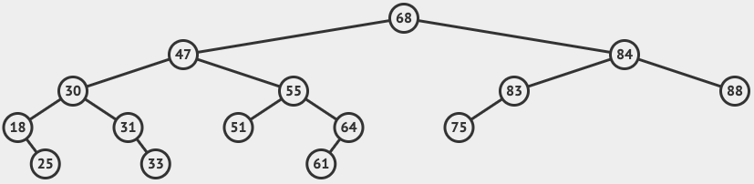
A binary search tree (BST) is a rooted binary tree data structure. It consists of a root at the top of the tree with accompanying child nodes. The root and nodes have either zero, one or two child nodes that form left and right subtrees.

Binary search trees have to satisfy the binary search property, meaning values in the left subtree must always be less than the parent and values in the right subtree must always be greater than the parent.

Example binary search tree
Read More

UML State Machine Diagram

State machine diagrams were covered as part of the Software Engineering module (COM00144M) during my MSc studies with the University of York. This post will detail my findings and provide information and examples on how to create state machine diagrams.

What is a state machine diagram?

State machine diagrams are used to model the events an object can go through. They visualise the steps of a process and show the different paths that can be taken from one state to another during its lifetime.

States

Each state is shown by a single rounded rectangle, the name of the state is written inside.

State machine state example

States can contain further optional detail in the form of these additional properties:

  1. Entry – An action that is performed on entry to the state
  2. Do – An action that is performed while in the state
  3. Exit – An action that is performed on exit of the state
  4. Defer – An action that occurs when the current state is exited and triggered from another state
State machine expanded state example
Read More

UML Sequence Diagram

Sequence diagrams were covered as part of the Software Engineering module (COM00144M) during my MSc studies with the University of York. This post will detail my findings and provide information and examples on how to create sequence diagrams.

What is a sequence diagram?

A sequence diagram is a type of interaction diagram that shows interactions via time sequence. Each object has a vertically descending lifeline with operation arrows from the source to target lifeline.

Read More

UML Use Case Diagrams

Use case diagrams were covered as part of the Software Engineering module (COM00144M) during my MSc studies with the University of York. This post will detail my findings and provide information and examples on how to create use case diagrams.

What is a Use Case Diagram?

A use case diagram is part of the unified modelling language (UML). They are responsible for detailing high-level functionality and system scope by showing user interactions.

The diagrams consist of four main components:

  • Actors
  • Use Cases
  • Relationships
  • System Boundaries
Read More

UML Class Diagrams

As part of the MSc degree with the University of York, I have studied the Unified Modelling Language (UML) during the Software Engineering module (COM00144M). A section of this work has been related to class diagrams.

What is a Class Diagram?

A class diagram is a way to statically represent the structure of a system. This is achieved by modelling the systems classes, attributes, operations and relationships between objects involved.

Class diagrams come in different perspectives, this depends upon the stage of design.

  • Conceptual: represents the early stage concepts in the domain
  • Specification: focuses on the interfaces of abstract data types
  • Implementation: describes how classes will implement interfaces
Read More

Object Constraint Language

The object constraint language was covered as part of the Software Engineering module (COM00144M) during my MSc studies with the University of York. This post will provide information on why OCL is used and examples of how you can implement OCL.

What is OCL?

The object constraint language (OCL) is a declarative ISO standard language created by IBM. OCL was developed to help relieve limitations with UML modelling and to allow the specification of more precise aspects of a system design. OCL is a part of the Unified Modelling Language (UML) set by the Object Management Group (OMG) as a standard for object-oriented design.

OCL is a declarative and side-effect free language which means the constraints only enforce rules, they do not assign values or modify the system.

Some usages of OCL include:

  • Invariants specify constraints that have to equal true during the instance of an objects lifetime
  • Preconditions specify constraints that have to equal true before a method is run
  • Postconditions specify constraints that have to equal true after a method is run
  • Initialisation specify default property values
Read More