Use case diagrams were covered as part of the Software Engineering module (COM00144M) during my MSc studies with the University of York. This post will detail my findings and provide information and examples on how to create use case diagrams.
What is a Use Case Diagram?
A use case diagram is part of the unified modelling language (UML). They are responsible for detailing high-level functionality and system scope by showing user interactions.
The diagrams consist of four main components:
- Actors
- Use Cases
- Relationships
- System Boundaries
Actors
There are two types of actor that can be shown in a use case diagram:
Primary Actor
A primary actor is the user who interacts directly and initiates the usage of the system. These actors are shown on the left hand side of the system boundary.
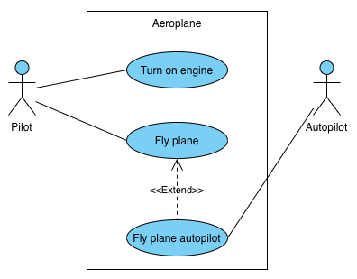
An example of a primary actor would be a pilot turning on an aeroplane engine.
Supporting Actor
A supporting actor (also sometimes known as secondary actor) is the user who provides a service or a form of information to the system. These actors are usually shown on the right hand side of the system boundary, however this placement is not required by the standard but recommended for visual preference.
An example of a support actor would be an autopilot taking control of an aeroplane mid flight.
Use Case
A use case describes how an actor will achieve a task via the system. They are depicted by oval shaped circles.

Relationships
Relationships show links between objects in use case diagrams, there are multiple different types of relationship to represent.
Association
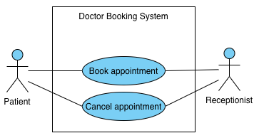
An association is a link between an actor and a use case. Each actor must be associated with at least one use case but can be associated with many. Multiple actors can be associated with a single use case.
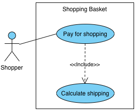
Include
An include relationship shows a dependency between a base use case and an included use case. When the base use case is executed the included use case is always executed.
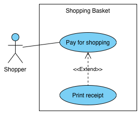
Extend
An extend relationship shows a dependency between a base use case and an extendable use case. When the base use case is executed the extended use case is sometimes executed.
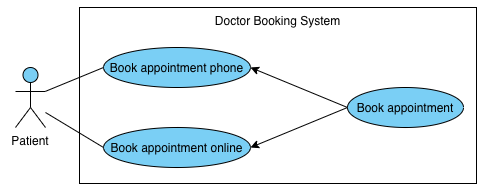
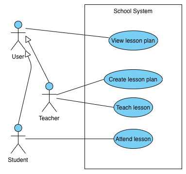
Generalisation
A generalisation is a way of showing inheritance using an arrow pointing to the parent from the child for both actors and use cases.
An example for use cases is where specialised child use cases exist, such as booking a doctors appointment over the phone vs online but they both still require the parent action of booking the appointment in the system.
An example for actors is where specialised child actors exist, such as a teacher and a student. Both actors may have specific use cases only they can perform but there may also be general user use cases that any actor can perform.
System Boundaries
A system boundary is a rectangle that is drawn around use cases of a system to visualise the internal use cases vs the external actors. The title of the system is written inside centrally at the top. You can see in all of the examples above that the actors have been executing use cases that are inside of the system.