State machine diagrams were covered as part of the Software Engineering module (COM00144M) during my MSc studies with the University of York. This post will detail my findings and provide information and examples on how to create state machine diagrams.
What is a state machine diagram?
State machine diagrams are used to model the events an object can go through. They visualise the steps of a process and show the different paths that can be taken from one state to another during its lifetime.
States
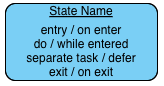
Each state is shown by a single rounded rectangle, the name of the state is written inside.

States can contain further optional detail in the form of these additional properties:
- Entry – An action that is performed on entry to the state
- Do – An action that is performed while in the state
- Exit – An action that is performed on exit of the state
- Defer – An action that occurs when the current state is exited and triggered from another state
Transitions
State changes are shown by lines with an arrowhead pointing in the direction of travel.
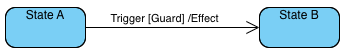
You will note the line from one state to another state has three labels, these indicate:
- Trigger – the action that causes the state change
- Guard – this constraint must be true for state change to occur
- Effect – an action that occurs due to the state change taking place
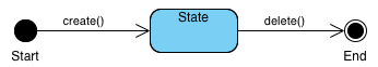
Start and end states
Start and end states are shown by similar but slightly different circles. The start point is a solid black circle where as the end is a ringed black circle.
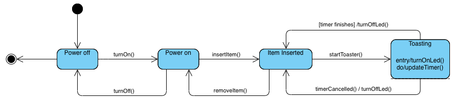
State machine diagram example
The following state machine diagram is an example of a basic toaster use case.