As part of the MSc degree with the University of York, I have studied the Unified Modelling Language (UML) during the Software Engineering module (COM00144M). A section of this work has been related to class diagrams.
What is a Class Diagram?
A class diagram is a way to statically represent the structure of a system. This is achieved by modelling the systems classes, attributes, operations and relationships between objects involved.
Class diagrams come in different perspectives, this depends upon the stage of design.
- Conceptual: represents the early stage concepts in the domain
- Specification: focuses on the interfaces of abstract data types
- Implementation: describes how classes will implement interfaces
Class Diagram Relationships
An important part of class diagrams is representing relationships between classes, this can be done in different forms.
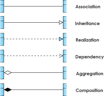
Association
An association is a relationship between classes, it is represented as a solid line between the classes. If an association exists then it signals the classes have a need to communicate with one another.
Arrows can be used between the classes to show the direction of navigation. If there are arrows on both sides then this is known as a bidirectional association.
Aggregation and Composition
Aggregation and composition are both subsets of associations. In both types, an object of one class owns the object or another class however they have slightly different use cases.
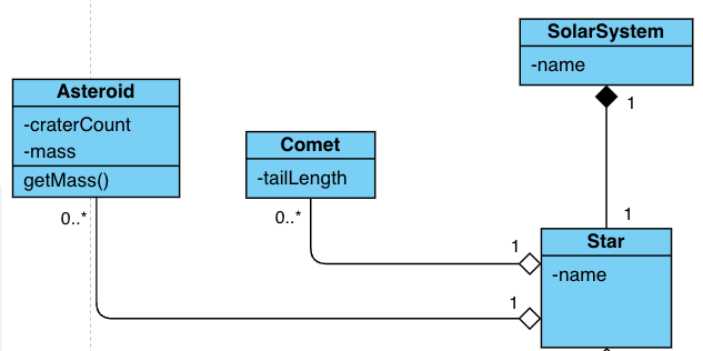
In the above example class diagram, you can see there are two types of diamond. The solid filled diamond shows composition and the empty diamond shows aggregation.
Aggregation
In an aggregation relationship, the child object can exist even if the parent object is destroyed.
For example in the above class diagram you can see we have a Star which represents the parent object and an Asteroid and Comet which both represent aggregation child objects. If we were to delete the Star then the Comet and Asteroid could still exist, they would just be lost in space.
Composition
In a composition relationship, the child object can not exist if the parent object is destroyed.
For example in the above class diagram we again have the SolarSystem but this time a Star is associated via a composition relationship. This means that if the Star is deleted then the SolarSystem cannot exist.
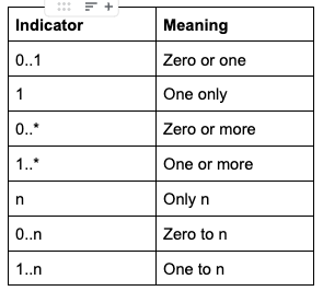
Multiplicity
Multiplicity defines the minimum and maximum amount of object instances relative to an association.
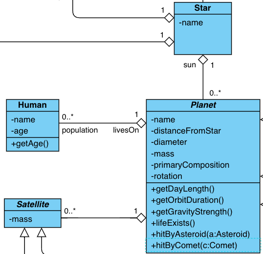
In the above class diagram you can see we have used multiplicity in a number of ways.
- Planet -> Human – one planet could have anywhere between zero humans and unlimited amount of humans living on it, therefor we represent this using
0..* - Human -> Planet – one human will always live on just one planet, this is why we have the single
1digit. - Planet -> Satellite – this carries the same logic behind
Planet -> Humanbecause a planet may have zero satellites or it may have an unlimited number - Satellite -> Planet – in this use case a satellite is always linked to a planet
- Planet -> Sun – in the solar system a planet has just one star, the sun so we use
1 - Sun -> Planet – the sun currently has multiple planets orbiting but in the future that may not be the case. Strictly speaking we could count the planets and dwarfs and use 0..x if we knew the upper value of x
Generalisation / Inheritance
Generalisation is the term used for parent-child relationships, this is sometimes referred to as superclasses and subclasses. Generalisation enables inheritance from general classes to specialised classes.
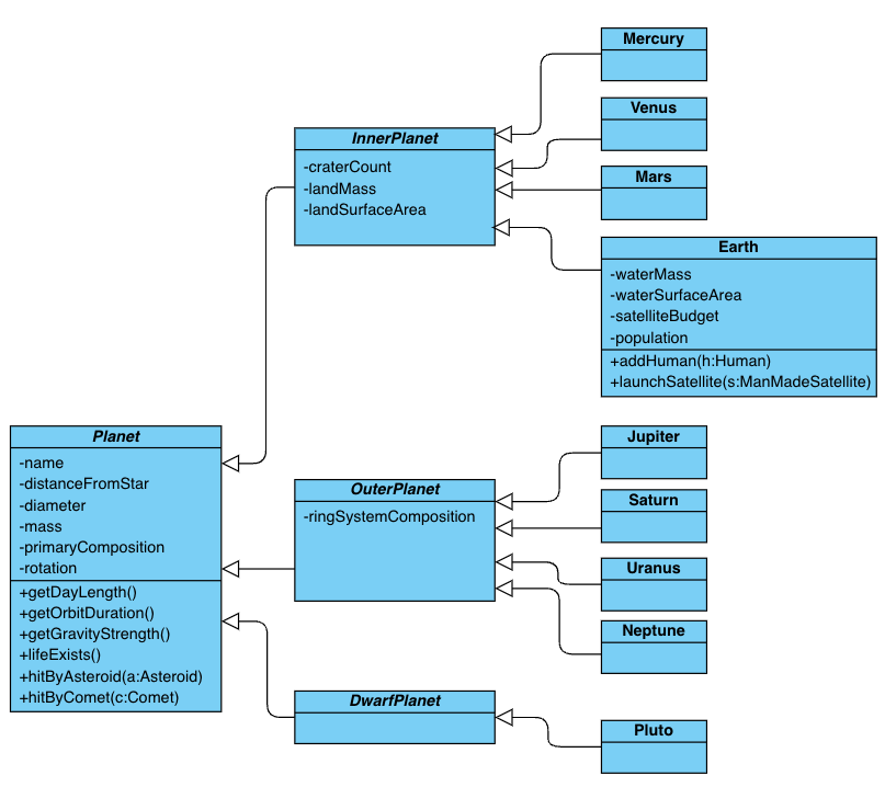
In the above example we can see the abstract class Planet is at the top of the hierarchy and then we have further abstract Planet classes representing the area of the solar system the planets are within, following by real Planet classes such as Earth. Here the most generalised class would be Planet and the specialised classes would be on the right hand side, including Earth. We would expect in a more complete class diagram to see more specialised properties that only apply to the child classes, representing specialisation.
Realisation
Realisation is a relationship where a contract is enacted and guaranteed to be carried out by the implementor. This is more commonly known as a class implementing an interface.
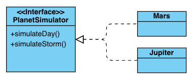
In the above example you can see we have a PlanterSimulator interface. Imagine if we want to show examples of simulating either a day or a storm, both of these operations would have very different logic and behaviour so it wouldn’t make sense to use inheritance. Instead we use an interface to enforce the implementors to both create these methods but using their own logic. This way the behaviour will be different and we can be sure both child classes will have the ability to carry out the required tasks in the PlanetSimulator contract.
Dependency
A dependency relationship defines that two or more objects depend on one another. This kind of relationship can be useful to represent when changes to one class would affect another class.