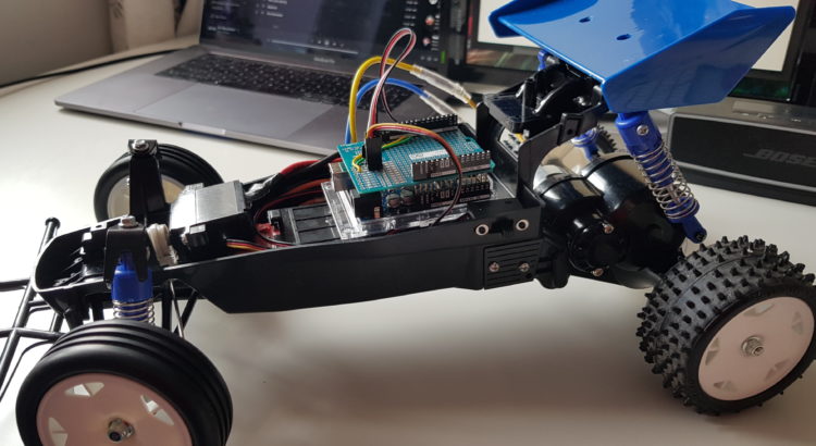
In the previous post the Tamiya RC car was built and we covered the electronic components. This gave us the knowledge required to look at replacing the factory components and control the RC car via code! Now let’s look at adding an Arduino for custom functionality.
Setting up the hardware
For this step I will be using an Arduino board to replace the receiver. This means the car will no longer have any radio transmission. Instead the servos and electronic speed controller will be controlled via code written to the Arduino board.
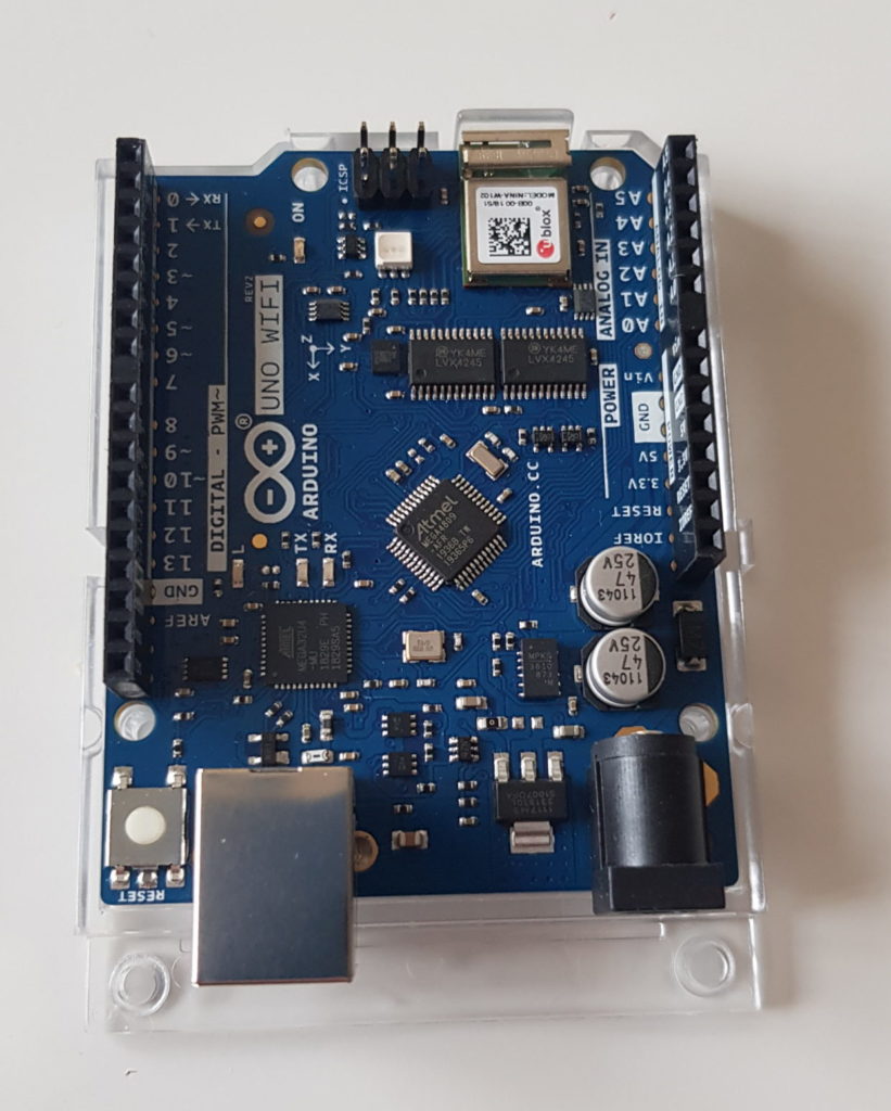
I’ve chosen to use the Arduino Uno WiFi Rev2 board because it has the required power and functionality. It also has the added bonus of WiFi which will be useful to enable Internet remote control of the car. Take a look at the above link for more information on the technical specification of the board.
I also bought an Arduino Proto Shield Rev3. With some soldering this will sit on top of the Arduino Uno board and allow custom ports and wiring. The servos can then be quickly plugged in or unplugged.
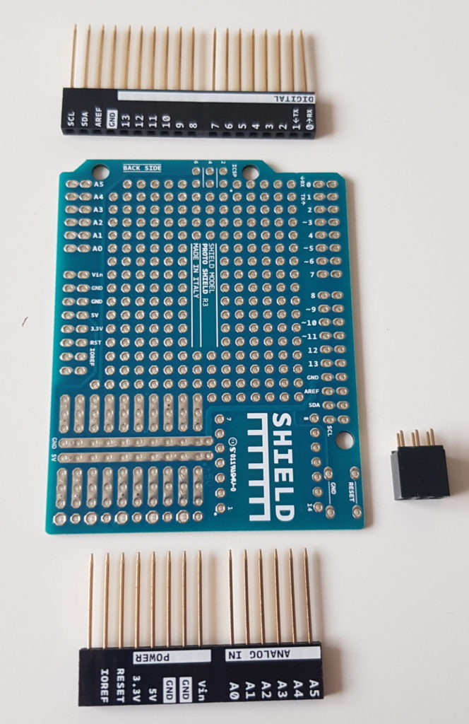
The first step is to act on the above and do the custom modification to the proto shield. This involves adding two 3 pin connectors to the board over the 5V, gnd and 8, 9 digital inputs. You can see the outcome of doing that in the following photos:
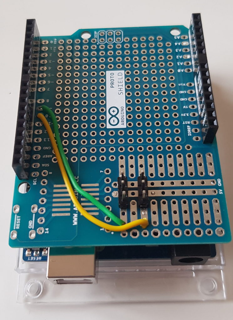
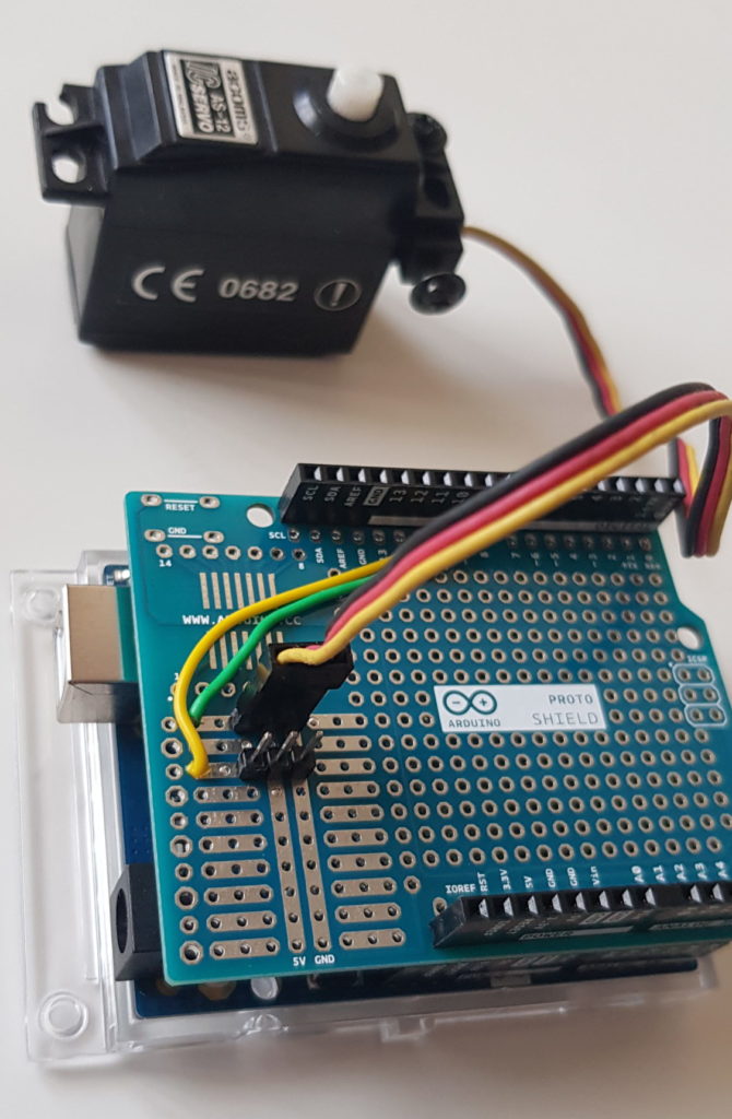
Both the three pin connectors shown allow for a servo and electronic speed controller to be directly connected, powered and controlled by the Arduino.
Writing Arduino code
We are ready to write and apply some custom code to the logic. I highly recommend that you try your code with the servos not connected to RC car parts to begin with. It is far too easy to accidentally upload some code that runs a servo at full speed and your fully built RC car flies off your desk and cables rip apart, drinks go flying and screens smash etc… I warned you!!
At this point we can open up the Arduino IDE to start writing some c++ code. There’s many tutorials out there on how to use this IDE to upload code to the board and it’s straightforward. A quick Google will get you on the right track.
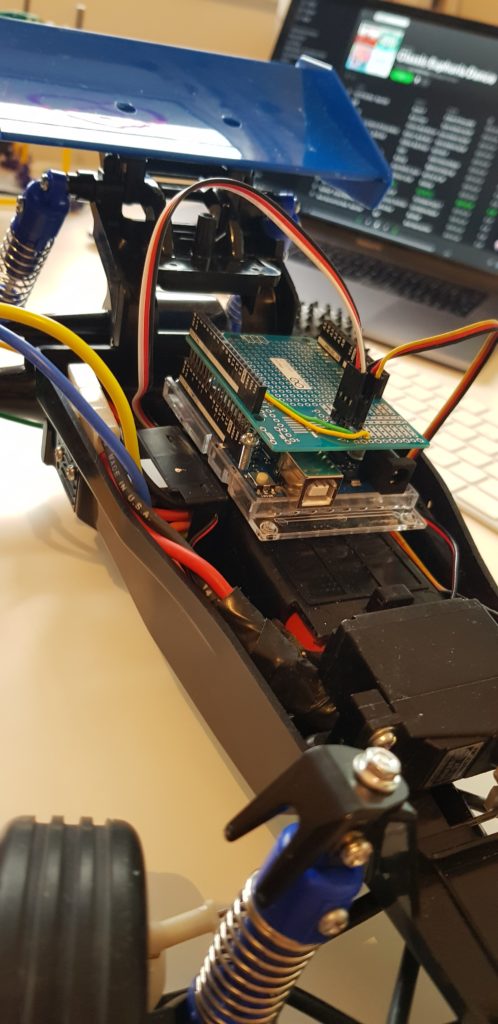
The first step to setup the code is to declare which digital pins the two servos are connected to. I mentioned earlier that I’ve chosen to use pins 9 and 10. If you have good eyesight you might be able to see that on the board in the photos.
Fortunately there’s an Arduino Servo class ready for us to implement: https://www.arduino.cc/en/reference/servo
#include <Servo.h>

Servo steering;
Servo throttle;

void setup()  {
    throttle.attach(9);
    steering.attach(10);
}
Our first movement
Simple, now we have two Servo variables that we can write to and control the physical Servos. The next tricky bit is figuring out the ranges of your Servo, most Servos range from 0 to 180. In the acceleration configuration there’s a neutral range around 90-100 with forward and reverse above and below those ranges respectively. The higher or lower the value from the neutral the faster your speed. In the steering servo configuration 90 is straight, 0 -> 89 is left and 91 -> 180 right. The higher this value the tighter the turn.
The below is a very simple script to demo forward movement and stopping. The car will first steer straight and then move forwards at a slow speed for two seconds before stopping for five seconds. This gives us a few seconds to grab the car before we realise our speed controller works in a different range and accelerates into the nearest wall at full speed… (you’re testing without the Servos attached to the car though, right?!).
#include <Servo.h>

Servo steering;
Servo throttle;

void setup() {
    throttle.attach(9);
    steering.attach(10);
    // Before we move the car, reset the steering
    steering.write(90);
}

void loop() {
    // Accelerate forwards at a slow speed for two seconds
    throttle.write(105);
    delay(2000);

    // Enter the neutral range for 5 seconds
    throttle.write(90);
    delay(5000);
}
If the above was a success we can try getting our car to turn around in circles by itself. The following code will repeat an automated three point turn:
#include <Servo.h>

Servo steering;
Servo throttle;

int accelerationSpeed = 89; // Slowest accelerate speed 90
int reverseSpeed = 104;     // Slowest reverse speed 102
int neutral = 91;
int brake = 180;

int noTurn = 90;
int leftTurn = 0;
int rightTurn = 180;

bool debug = true;

void setup() {
    if (debug) {
        Serial.begin(9600);
    }
    throttle.attach(9);
    steering.attach(10);
}

void Logger(String message) {
    if (debug) {
        Serial.println(message);
    }
}

void MoveBackward() {
    Logger("Move: reverse");
    throttle.write(reverseSpeed);
}

void MoveForward() {
    Logger("Move: accelerate");
    throttle.write(accelerationSpeed);
}

void Brake() {
    Logger("Move: brake");
    throttle.write(brake);
}

void Stop() {
    Logger("Move: stop");
    throttle.write(neutral);
}

void SteerLeft() {
    Logger("Steer: left");
    steering.write(leftTurn);
}

void SteerStraight() {
    Logger("Steer: staight");
    steering.write(noTurn);
}

void SteerRight() {
    Logger("Steer: right");
    steering.write(rightTurn);
}

void loop() {
    SteerLeft();
    MoveForward();
    delay(2000);

    Brake();
    delay(250);

    Stop();
    delay(2000);

    SteerRight();
    MoveBackward();
    delay(2000);

    Stop();
    delay(2000);
}
Summary
You should now have an RC car that does something similar to the one I made in this video:
That’s all for part two. Have a play around with the code and see what you can make the car do. There’s a couple of projects out there that have incorporated sensors at this point. They would stop the cars movement before it drove into anything. That could be quite useful functionality if you’re looking for more small additions.
I’ve created a GitHub repository for the above code samples and I’ll be adding more along the way. Check it out: https://github.com/dant89/arduino-rc-car
Stay tuned for part 3 coming in the near future. The next step will be using the WiFi on the Arduino board to allow remote control over the Internet.
2 thoughts to “Arduino RC Tamiya – Part 2”